Core concepts
Robots is a Rhino and Grasshopper toolkit for offline industrial-robot programming. The core loop is simple: load a robot system, define the objects used by the job, create targets, build a program, review warnings and errors, simulate, then save or upload controller code.
This page is the map. Detailed behavior for Target, Speed, Zone, Frame, Tool, Program, and the other typed objects lives in Parameters. Component-specific workflow notes live in Components.
- Load a Robot System from a library.
- Define or load the Tool, Frame, Speed, Zone, and Command values needed by the job.
- Create Targets or Toolpaths.
- Create a Program from the robot system and target data.
- Review warnings and errors.
- Simulate motion and, when needed, check collisions.
- Save or upload generated controller code.
The same model is used from Grasshopper, Rhino scripts, and .NET applications.
Grasshopper inputs and generated program data use fixed units, regardless of the Rhino document unit system.
| Quantity | Unit |
|---|---|
| Length | Millimeters |
| Angle | Radians |
| Weight | Kilograms |
| Time | Seconds |
| Linear speed | Millimeters per second |
| Angular speed | Radians per second |
| Linear acceleration | Millimeters per second squared |
| Angular acceleration | Radians per second squared |
Robot library XML has a few legacy conventions of its own: revolute joint ranges, revolute joint speeds, and DH angle fields are written in degrees. See Robot libraries.
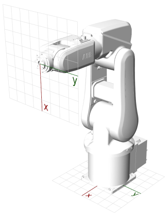
Robots uses a right-handed coordinate system.
-
World coordinate system: the Rhino document coordinate system. The
Baseinput onLoad Robot Systemplaces the robot system in this space. - Robot coordinate system: the robot base coordinate system. By default, robots are placed on World XY. The X axis points away from the front of the robot and the Z axis points up.
- Tool coordinate system: the TCP coordinate system relative to the flange. The Z axis points away from the flange and the X axis points downward.
- Frame coordinate system: the target work coordinate system. Target planes are interpreted relative to their frame. See Frame Parameter.
| Object | Role | Details |
|---|---|---|
| Robot System | The robot cell: arm, external axes, IO, meshes, controller family, and postprocessor. | Robot System Parameter |
| Tool | End effector data: TCP, load, centroid, preview mesh, collision mesh, controller tool references. | Tool Parameter |
| Frame | Work coordinate system, including optional coupling to an external mechanism or coordinated robot. | Frame Parameter |
| Speed | Speed, acceleration, external-axis, and optional time settings. | Speed Parameter |
| Zone | Stop point or fly-by approximation settings. | Zone Parameter |
| Command | Target or initialization action, such as messages, waits, IO, stop, or custom controller code. | Command Parameter |
| Target | A joint or Cartesian robot pose plus tool, frame, speed, zone, command, and external-axis values. | Target Parameter |
| Toolpath | Ordered targets passed as a single value. | Toolpath Parameter |
| Program | Checked target data, warnings, errors, simulation, duration estimate, and generated code. | Program Parameter |
Create Program is the main validation boundary. It checks target counts, axes, frames, tools, payloads, kinematics, motion support, command support, and postprocessor support before code is saved or uploaded. The detailed checklist and warning/error behavior are documented in Program Parameter.
Manufacturer support is not uniform. A program that is valid for one robot family can be rejected for another. See Manufacturer support.
Robots programs contain a kinematic, non-dynamic simulation for reviewing sequence, reach, sampled motion, fly-by zones, and collision geometry. The detailed simulation scope and limitations live in Simulation.
- Parameters: exhaustive reference for the typed Robots objects.
- Components: component workflow behavior.
- Workflow guide: how to organize a complete Grasshopper definition.
- Manufacturer support: controller family differences for tools, frames, commands, motion types, and postprocessors.
- Robot libraries: XML and 3DM library conventions.
- Troubleshooting: common errors and warnings.